CARPENTER’S KNOWLEDGE IN SETTING OUT ROOFS AND BUILDINGS FROM SAXON TO THE LATE MEDIEVAL PERIOD
The Sections below cover carpenter’s knowledge in setting out roofs & buildings from Saxon to the late medieval period. By selecting them you will be taken to the associated content on this page.
INTRODUCTION
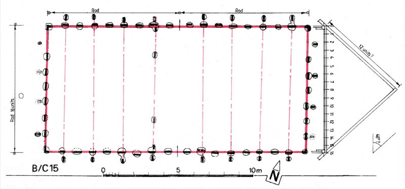
This study is the result of my observations and research while working on medieval timber frame buildings both before my retirement and later from studying many books, papers and publications on Anglo-Saxon and Viking buildings. The archaeology of these buildings shows floor plans with rows of postholes, especially, the excavations at Market Field at Steyning Sussex[1], Cowdery Down Hampshire[2] (Fig. 1), at the Viking sites 16-22 Coppergate in York[3], and the river front excavations in Dublin[4] and London[5]. There are many theories and reconstructions of Saxon/Viking buildings but no insight or understanding as to how the Saxon builders set them out and constructed them. Much speculation has been printed in archaeological journals and there have been many attempts at constructing them in open air museums. I realised that many Saxon buildings had double square floor plans (Fig. 1) [The length of the building is twice the width] and it became obvious that they were set out using a rod equal to the span or width of the building. (Figs. 1 and 2)
[1] Mark Gardiner Excavations of a Late Anglo-Saxon Settlement at Market Field Styning 1988-89, Sussex Archaeological Collections 131 (1993) 21-67
[2] Martin Millett and Simon James, Excavations at Cowdery’s Down Basingstoke, Hampshire, 1978-81, Archaeological Journal 140 (1983)151-279
[3] Richard Hall, Anglo-Scandinavian Occupation at 16-22 Coppergate York, Defining a Townscape, York Archaeological Trust 2014 523-814
[4] Hilary Murray Viking and Early Medieval Buildings in Dublin, BAR British Series 119 (1983) 1-215
[5] Valerie Horsman, Christine Milne and Gustav Milne Aspects of Saxo-Norman London: 1 Building and Street Development, London and Middlesex Archaeological Society (1988) 6-123, Gustav Milne Timber Building Techniques in London 900-1400, London and Middlesex Archaeological Society (1992), David Bowsher, Tony Dyson, Nick Holder and Isca Howell, The London Guildhall, Museum of London, Monograph 36, 3 volumes. 2007

Figure 1 Building 15 Cowdery Down Hampshire by Martin Millett and Simon James 1978-81, the red rectangle represents the wall plate and the end tie-beams fixed on top of the vertical wall plank posts. Tie beams are shown by dotted lines across the building.
Drawing amended by Paul Reed

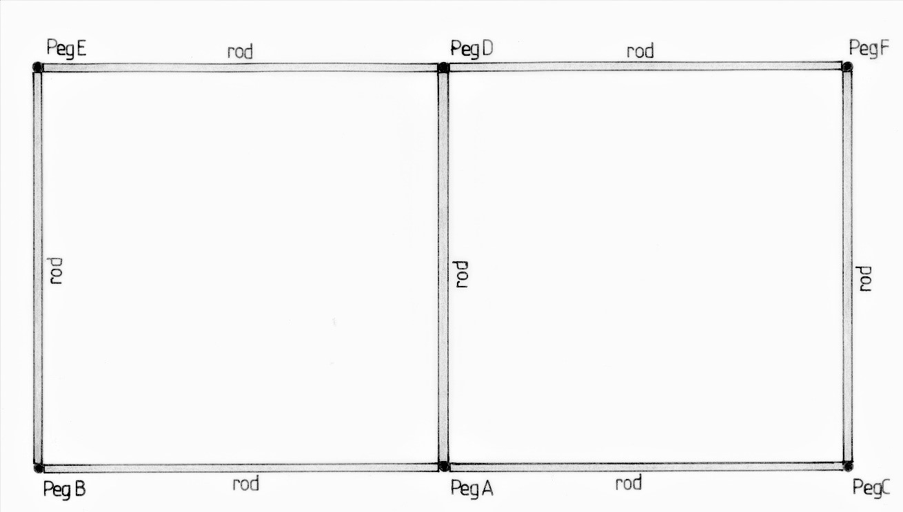
Figure 2 Setting out a double square using a rod. Drawn by Paul Reed
A PDF of this page is available that includes annotated notes for the rest of the article.
(Note: It will open in a new browser tab)
MAKING AND USEING A ROD
The first thing the Saxon builder would have required was a rod. This was a long straight pole, which he would have taken to a growing wood to measure available trees that were suitable for the building; the trees would have needed to have the length and width to be cut into tie beams, wall plates, and rafters. If so, he would place the rod up against the growing tree and cut a notch at the top of the rod to give a standard length of the timber available. With this gauge, the builder would go to the building site and set out the building, using the rod and long pegs as follows (Fig. 2).
First the builder secures a centre setting-out peg A, then from peg A he lays the rod on the ground to mark the position of peg B. The rod is then moved back to peg A and laid on the ground to mark the position of peg C. The setting-out Peg C is sighted up with pegs A and B to make a straight base line, i.e., the length of the building. From peg A, the rod is placed on the ground at roughly a right angle to peg A to locate the position of peg D, the width of the building.
From peg D, pegs E and F are located, and the procedure used for setting out the base line is repeated. The distances between pegs F and C and between E and B can be checked with the rod.
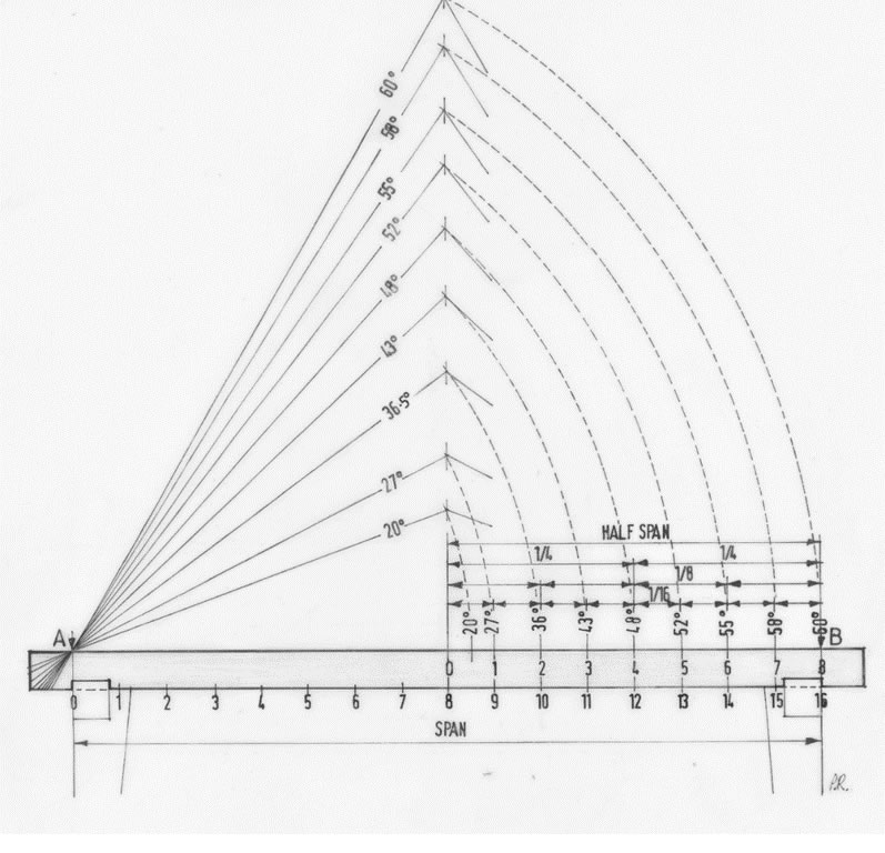
The building has been set out without using a square, a line or measurements; in this case the floor plan accurately follows the layout of building 15 at Cowdery’s Down in Figure 1, wall plates coloured red. Building 14, also on the same site, not illustrated, is also set out using a rod. The building is half a rod longer than building 15 using the same setting out principal. Figures 1 and 4 shows the rod on the tie beam marked out in 16 units giving the rafter length of 12 units a roof pitch of 48° which has been found on some Saxon Buildings, e.g., the Saxon chapel at Bradford on Avon , and Odda’s Chapel in Gloucestershire . Old St Helens Church in Hastings has a roof pitch 43° all based on the use of the 16 units of the rod.
SAXON WOODWORKING SKILLS
There is a wealth of evidence of Saxon and Viking craftsmanship in ship building, metal working and the production of high-quality steel to make weapons and tools. Intricate gold and silver working as seen in our museums, found as grave goods, Sutton Hoo in Suffolk being a good example and the Staffordshire hoard . The Saxon Graveney boat found in Kent , now in the care of the Greenwich Maritime Museum, and Viking ships on display in the museums in Scandinavia are amazing examples of woodwork craftsmanship. Even on our doorstep the Saxon door, still in use in Westminster Abbey, shows superb craftsmanship in timber for all to see close-up .
When there is good archaeological evidence available, it is not always used by curators of open-air museums. For example, there is much evidence that Saxon carpenters used saws, adzes, augers, chisels, planes and many other recognisable wood working tools, not just axes and augers! but they are not used, mentioned or referred to on reconstruction buildings! This knowledge of early medieval carpenters has been explained in detail in my articles listed on this website from the Saxon period to the late medieval period and into the 18th century where this knowledge had continued unbroken, handed down from master craftsman to apprentice.
SETTING OUT WITHOUT NUMERIC MEASUREMENT
The evidence from my research has been demonstrated on many buildings as shown in the list of articles on this website. The technique was used not only to set out domestic buildings, barns and large halls but also churches and cathedrals. It was all based on the use of a length of string or cord, and did not require any numeric measurements or geometry.
Such a simple procedure, using large dividers and a rod, became a method of setting out which has lasted for thousands of years and was only out-dated by the introduction of scaled drawings on paper produced by architects and surveyors in the 17th and 18th century. These early professionals used tee squares, brass set-squares and protractors on a drawing board and the resulting drawings were then handed to the builder to build the building. By the end of the 18th century the length of string for measuring and setting out became obsolete.
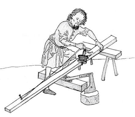
Throughout history, cord or string has been an important part of the craftsman’s kit (Fig. 3). Whilst one immediately thinks of bricklayers and stonemasons working to a line, most building crafts need a length of string for one use or another. Apart from its importance as an aid to setting out in constructing buildings as diverse as the ancient pyramids, Stonehenge and our impressive cathedrals, the simple line has also been responsible for achieving a vertical plumb line and for drawing an ellipse.
Modern-day technology has dispensed with the many uses of the handy string line. The laser is now found in the modern workman’s toolkit to level, plumb and set out buildings. The historic use of the string line has almost been forgotten.
The early medieval craftsmen were almost certain to have used string or cord to measure and set out their buildings. Villard de Honnecourt, in his notebook (circa 1250) , shows illustrations using string for setting out examples and solving problems. Salzman3 mentions carpenters using lines or rods for measuring.

Figure 3. measuring a plank, Catherine of Cleves’ Book of Hours, MS 917, fol. 105, traced from Illustration No.358, p120, Günther Binding, 2004, Medieval building Techniques
THE PASSING ON OF KNOWLEDGE & SKILLS
Medieval master craftsmen would have met regularly in their lodges or guilds to discuss methods of construction, problem-solving and how to use practical geometry, dividing up a circle and creating angles, not necessarily attributing it to Pythagoras or Euclid. This knowledge, while closely guarded by the guild, would be passed down from master to apprentice; when the apprentice was qualified, he became a master craftsman, keeping the knowledge secret in the same way to protect the craft.
Euclid’s Elements was translated into Latin by Adelard of Bath in the mid-twelfth century, most likely from the Arabic of the Moors in Spain. The Roman foot, 115/8in. (296mm), may have been used by Anglo-Saxon builders. The Saxon foot has been studied by Ferne , Huggins , Bettess and Marshall and Marshall with inconclusive results.
THE STANDARDISATION OF MEASUREMENTS
Regulating measurement originated with Henry III or his son Edward I sometime between 1216 and 1307. The original yard was a length devised by one of these monarchs, based apparently on a rod of iron. However, not only is there no record of this early yard, crucially, it also seems not to have been widely used. It was only with the Tudors that two important Acts of Parliament set out standard measurements of length and area: the yard, the rod and the acre. Henry VII in 1497 produced a fixed yard called the Exchequer Standard, which in 1588 was slightly revised by Elizabeth I. Moreover, to cement acceptance of the official weights and measures, Elizabeth appointed inspectors to enforce their use. These measurements, the Exchequer Standard first established by Henry III or Edward I, were calculated as follows:
3 Dry barleycorns laid end to end = 1 Inch
12 Inches = 1 Foot
3 Feet = 1 Yard
5½ Yards (16½ft) = 1 Rod
40 Rods in length and 4 in breadth = 1 Acre
Elizabeth’s yard, a rod made of bronze divided into feet and inches, could be accurately measured and reproduced, allowing her officials to secure in every borough in England the adoption of the new standard measures: yards, feet, inches, pounds and ounces, gallons and pints. Before Elizabeth’s decree, old measures were still being used. This made it very difficult for merchants and craftsmen working in different towns to trade with those from outside their immediate area.
Thus, builders would agree the ‘rod’ measure within their lodge or guild and all the craftsmen working on a particular building would use that same local measure. The rod of 16½ft (5.03m) is still used today for setting out a cricket pitch, which is 4 rods long = 22yds (or 1 chain). Garden allotments in England are still measured in rods and it was not until the eighteenth century that the 10ft (3.05m) rod came into common use. The yard that Henry III established, copied by Henry VII and Elizabeth I, is only 0.037in (0.094mm) shorter than the modern yard today.
I argue that earlier builders did not use a standard measure, but based the dimensions of the building on the materials available, using rods and string to define the components.
THE MASTER CRAFTSMAN
The medieval master craftsman was likely to have been a master carpenter or may also have been a master stonemason, or else they worked alongside one another. The Master would have had a basic knowledge of geometry, of how to use dividers and compasses to bisect angles and circles; and he would have had to use a straight edge and setsquare. He was capable of drawing full-size plans and elevations (there is evidence in the form of full-size drawings traced on the floors of Wells and York cathedrals) and especially of working-out proportions, having sufficient knowledge to build cathedrals and castles, structures where we know using a rod and a line was essential.
This knowledge of geometry to set out tracery windows held by the medieval master craftsman/architect was secret knowledge known only to them, as noted by authors such as Harvey, Salzman and Gimpel. But in the case of most buildings, this knowledge did not supersede the cord method for setting out which, as I will show, had been established since Saxon times.
MEDIEVAL CARPENTERS HAD A SIMPLER METHOD
Supporting my argument, the late Arnold Pacey in his book Medieval Architectural Drawings, published in 2007, states that there are no surviving medieval working drawings produced by craftsmen. Indeed, in private correspondence with the author, Pacey has said that he finds the basic argument of my theory convincing – namely, that the medieval carpenters didn’t need working drawings to set out roofs and buildings because they had a much simpler method that served them very well.
Such practical geometry, as we could describe it, would have been used, for example, to make a right-angled triangle with sides in the ratio of 3:4:5 (as in Pythagoras’s Theorem), which would have been applied to the setting out of right angles for buildings. In this instance, they would have used the rod or a cord 12 fixed units long with a knot at 3 units, another knot at 4 units and a final knot at 5 units; these three lengths, when joined together with a total perimeter of 12 units, make a right-angled triangle.
This practical application is still used today deploying two tape measures for the purpose. However, throughout medieval England this practical knowledge of Pythagoras does not appear to be used for making right angles and there is no evidence that the same formula was applied for obtaining common roof pitches, as the earlier, established cord method continued to be used in most buildings up to the seventeen to the eighteenth century.
It is very unlikely that a form of standard measurement was used by Anglo-Saxon builders, as we see from papers by Marshall & Marshall and others. These authors carried out surveys and analysis of Saxon building plans to see if there was a common length and width, but the summing-up of their findings was inconclusive. However, there was a common denominator of spans being around either 4.65m or 5.03m, the latter equivalent to the Elizabeth rod. However, Marshall and Marshall stated in their paper ‘the beam needed to be a structural timber able to span the width of the building’. This was my clue the tie-beam was the governing factor for most buildings.
THE ORIGIN OF THE DISCOVERY
At the Vernacular Architecture Group winter conference at Leicester in January 2017, in this instance on timber and trees, the resident master carpenter of the Weald and Downland Museum, Joe Thompson, gave a presentation in which he showed how the circumference of a tree can be measured with a piece of string, which is then folded twice to determine how much timber can be retrieved from a felled log. This ancient method was formalised by Edward Hoppus in the eighteenth century into tables measured in feet, providing easy references taken from a girth tape.
Tables and tape, used together, were published as Hoppus’s Practical Measurer in 1736. This method is still used by woodmen today to calculate the amount of timber obtainable from a standing or a felled tree. It was a brilliant practical demonstration of the use of a piece of string which set off the train of thought and my research into Anglo-Saxon woodworking which has led to my discovery.
SETTING OUT USING STRING
This simple procedure by folding a length of string or cord can be applied to the task of setting out historic buildings. The string is lightly stretched the length of the rod secured with a nail, is folded four times until 8 equal units are formed from the half span. This method of setting out does not require any form of numerical measurement, a protractor for angles, or any form of geometry. The main factors controlling the design of a medieval building were the length of the available timbers required for tie-beams (giving the maximum width of the building) along with the length of the posts (giving the height of the building) and the available size of building plot, as well as what the owner could afford.
Tie-beam lengths are usually between 5 to 7m, as in the Weald and Downland Museum’s Pendean Farmhouse 1605d, where the span is 5.03m, (16ft 6in the Elizabethan rod) and in the same museum’s Bayleaf Wealden Hall House, which is 6.55m wide. Widths depended on the available sizes and quality of local timber, as stated by Rackham in his studies on Prittlewell Priory and Grundle House.

Figure 4. Once the tie beam or rod has been divided into 16 equal units by folding a piece of string four times will produce 1 unit which can be set to dividers and paced out along the tie beam or rod to make the final adjustments. When a rafter timber is laid along the tie beam or rod and marked at A and at 12 will give a roof pitch of 48°, or at A and at 14 will give a roof pitch of 55° and so on. On this website: See Videos 1 Setting out the span of the building using cord/string into 16 units.
STANDARD ROOF PITCHES
Given these natural restrictions, how was the medieval building designed? How did the medieval carpenters manage to maintain common roof pitches of 43, 48, 52, 55 and 60o? Take, for example, the 110 roof pitches used on medieval domestic roofs in Kent, examined as part of the Royal Commission survey on the Historic Monuments of England (RCHME) conducted from 1968 to 1992. The angles of these different roof pitches were consistent throughout this period.
The choice of pitch was down to the carpenter pitching the roof as well as the materials he intended to use: thatch and shingles required a steeper pitch, say 52 or 55°, than tiles or slate roofs, which were usually 48° respectively. The results of a survey in the Midlands by Nat Alcock and Dan Miles, The Medieval Peasant House in Midland England, including 134 cruck and box-frame buildings, which again all have these same five constant roof pitches.
With many medieval buildings having stood for over 800 years, it must be borne in mind that most will have suffered from distortion arising from wear & tear, structural changes, general alterations, & decayed sole plates, posts and the like. It is therefore inevitable that tie-beams will have become out of level & wall plates distorted, resulting in an original pitch of, say, 52° ending up anywhere in the range of 50–53°. These discrepancies of perhaps several degrees are somewhat misleading. It is true that the historian, archaeologist & the surveyor can only record what is there.
However, to ascertain the true pitch of a roof, it has to be measured as accurately as possible, by measuring the rafter length, the span of the tie-beam or the height of the apex using sine, cosine or tangent. Assuming an original rafter & a tie-beam survive, this will take into account any historic distortions that may have occurred. Taking this into consideration, these pitches conform to the angles that result from rod & folded string. See Video 2 Setting out the pitch of the roof from the rod.
RESEARCH CONTINUES
Since the publication of Carpenter’s Knowledge in setting out Roofs and Buildings… in Vernacular Architecture in 2020 I have continued my research from domestic timber buildings to stone and timber tithe barns, churches and cathedrals with positive results. I have also extended my research to Europe and Scandinavia comparing churches, cathedrals and vernacular buildings. I have found some similarities basing the setting out of these buildings to my theory to see if there is a common link with the medieval craftsmen in England using the same method of setting out in Europe.
My research began by studying Saxon buildings in England, as the Saxons originally came from Denmark, North Germany, Friesland (North Netherlands) and settled in England, Belgium North France and Normandy. It would be most likely that my theory would be found in Europe, but it is not conclusive. Many roofs studied in Europe do not have the constant roof pitches we have in England; however, some roofs do compare in France, Belgium and in Scandinavia. This is on-going research which will require rigorous study of European vernacular and ecclesiastical buildings to see if there is any influence from the English school of Carpentry into medieval Europe.
This research is still ongoing...
Please check this website regularly for updates on new articles on how master craftsmen built medieval buildings - Isn't it interesting to know how long is a piece of string!
Get in Touch
Please get in touch using our contact form or by phone.
Mobile: 07711545618
